What is Boolean Algebra

When a state is either true or false it is known as Boolean. Computer circuits are built using this type of logic with logic gates. Boolean Algebra is a formal way of describing logical operations in truth tables. Boolean algebra is necessary in the modern computer sciences to support the programming of conditional statements.
|
A logic statement is a statement that evaluates to either True or False. For example "I am taking Computer Science A Level" is either true or false.
|
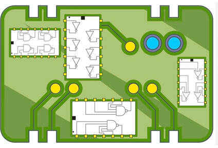
Representing Logic Gates
|
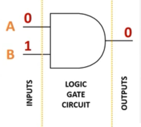
A digital electronic circuit in a computer system is typically made up of millions of logic gates. Inputs are represented by letters. In this example A and B. The output is usually represented as Q.
Inputs to logic gates are thought of as 1s and 0s which are actually high voltage (1) and low voltage (0). |
|
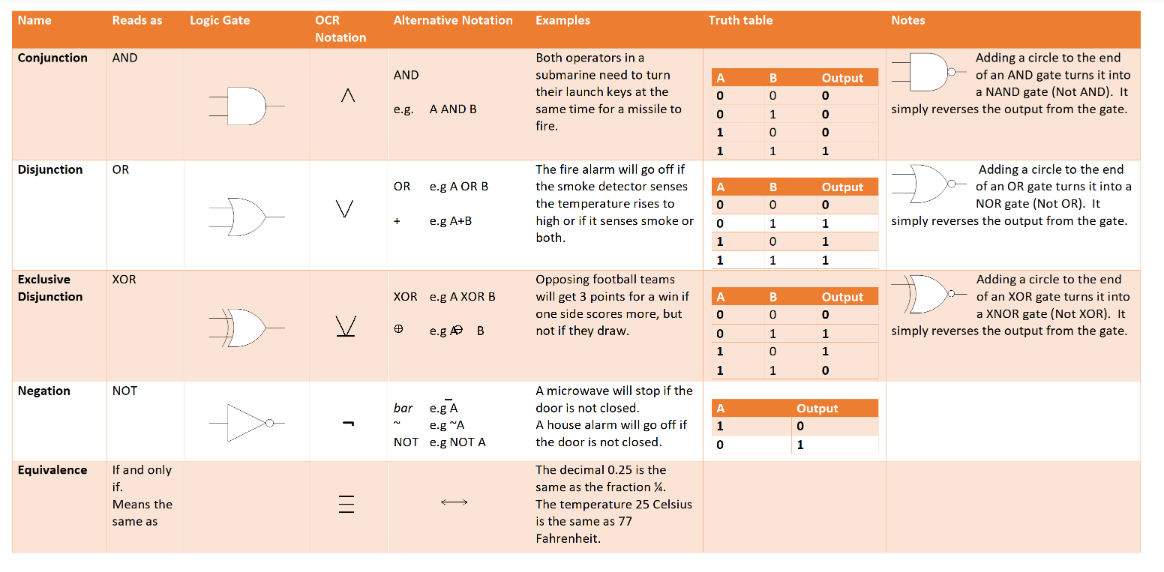
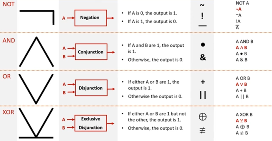
Logical Operators
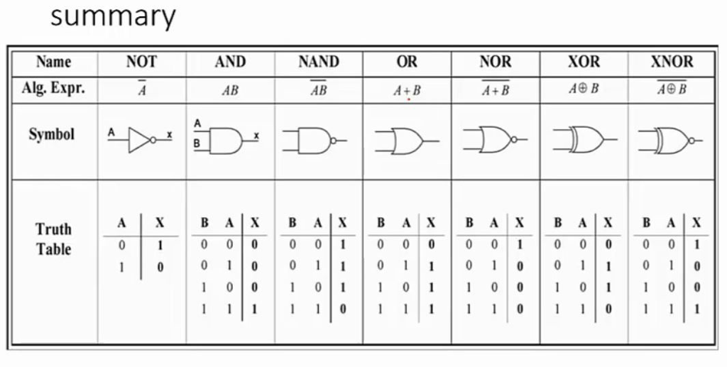
To define problems in Boolean algebra we use the special symbols shown here. Be aware that there are a lot of variations in symbols. However the large black symbols in the 2nd column will appear on your exams.
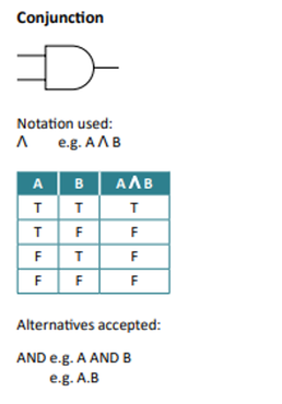
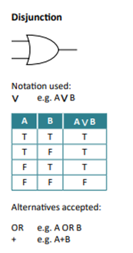
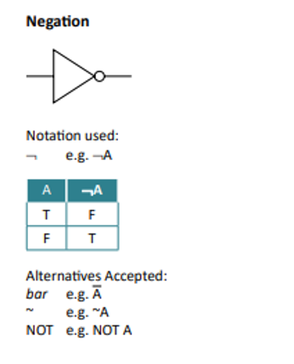
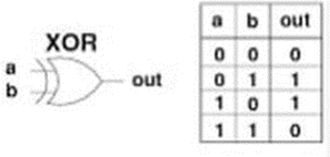
Logic Gates with their Truth Tables
|
|
|
|
|
|
|
|
XOR and OR - What’s the difference?
|
The OR gate outputs true if at least one of its inputs is true:
"You can be accompanied by a parent or over 18 to watch the film". |
The XOR gate output true if and only if one of its inputs is true:
"You can have chocolate cake or ice cream, but not both" |
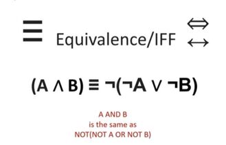
Equivalence
Equivalence means the same as.. like equals! Use three lines.
Karnaugh Maps
|
Since electronic circuits have millions of logic gates it would help to have the most efficient circuit containing the least amount of gates possible. Karnaugh maps are used to simplify these expressions to create most efficient circuit. This helps us to reduce the size of the circuit and therefore the cost to create it. It also reduces the execution time that it takes to fetch variables from memory.
|
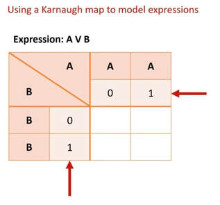
How do we create Karnaugh Maps?
|
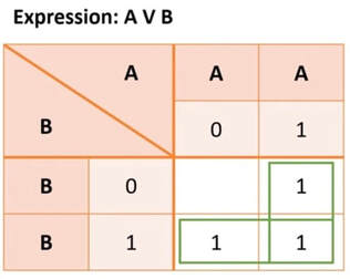
The expression here shows A or B.
|
|
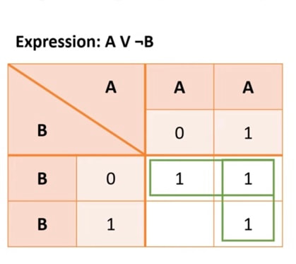
An example with NOTThe K-Map below shows A or NOT B.
Set up the map in the same way putting in A and B and the possible states. Start with A. Put 1s where A=1. Then with B put 1s where B is not 1. In other words where B=0. |
|
A longer example..
|
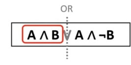
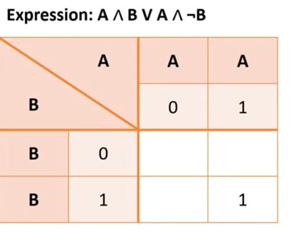
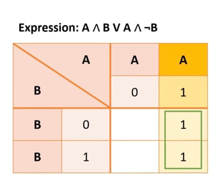
The expression here is A and B OR A and not B.
|
|
Then focus on the next part of the expression. Put a 1 where A is 1 and B is 0.
|
|
What do we get? A! So A and B or A and not B simplifies to just A. One very simple circuit!
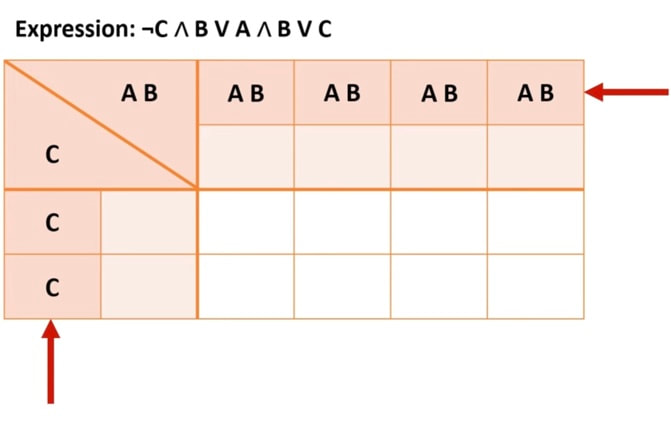
How do we simplify with more than two variables?
The following expression uses three variables: A, B and C.
We need to put two variables on one axis. It doesn’t matter which two.
|
De Morgan's LawDe Morgan's laws are very useful when working with algebraic expressions that contain the logical NOT operator.
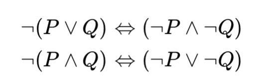
This related to negation. Here are two tautologies:
|
In plain English:
not ( P or Q) is the same as not P and not Q.
You could think of this as neither P or Q.
For example saying “I don’t like cricket or football” is the same as “I don’t like cricket and I don’t like football”.
not ( P and Q) is the same as not P or not Q
You could think of this as not both P and Q.
For example: “I don’t like both running and swimming.” is the same as “I either don’t like running or I don’t like swimming”.
Standard Logical Circuits - Full Adders, Half Adders and D-type Flip Flops
Processors only carry out simple instructions. D type flip flops, half and full adders handle these. Adders ( surprisingly handle adding! D type flip flops handle storing the value of a bit ( either 0 or 1).
Half Adder
A Half Adder is used to perform binary addition. As you can see, it uses an XOR gate and an AND gate. You can verify these gates by checking the values out put for Digit ( XOR gate) and COut ( AND Gate).
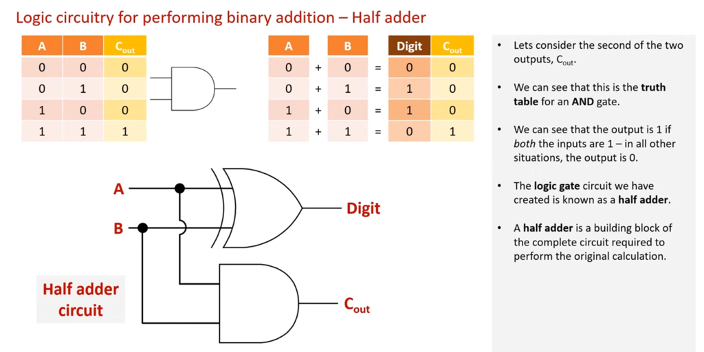
Half adders can add. But what happens if the addition results in a carry bit? Where does that go? You need a Full Adder.
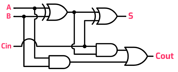
Full Adder
A full adder combines half adders to allow for more a further input: the carry bit.
|
Inputs:
A and B are the inputs into the first half adder. Cin is the carry bit from the previous half adder. Outputs: S is the sum of A,B and CIn. Cout is the carry bit ( either 1 or 0 ) |
|
D-Type Flip Flops
|
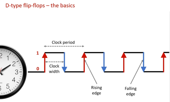
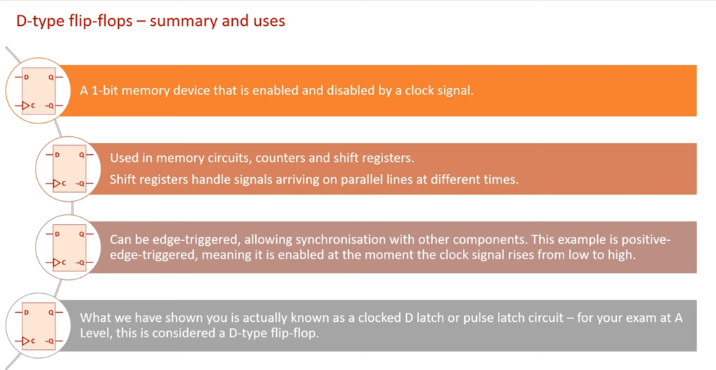
D-Type Flip Flops are used to store the value of one bit temporarily. A D-Type flip-flop is positive-edge triggered. This means that the output (Q) only changes when the clock pulse is either at a rising or positive edge. So the value is stored as the change is delayed.
|
|
|
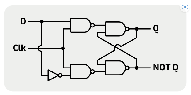
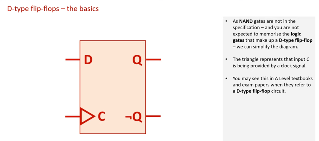
In this representation of a D-Type Flip Flop you can see the following inputs and outputs. The logic gates used are NAND and NOR. In other words NOT AND and NOT OR.
Inputs:
|
|
Cheat Sheets from Craig n Dave: